Table of Contents
Introduction
 Motion systems have been with mankind for millennia and even primitive control systems have been around for a few centuries. But it has only been in the last several decades that major advancements in truly controlled motion have been made.
Motion control systems take many forms. Old fashioned water wheels are early examples of motion devices. When man learned that the speed of the wheel could be controlled by changing the amount of water that passed under or over the wheel, the water wheel became a motion control device.
Open Loop and Closed Loop Systems
There are two basic types of motion control systems: open loop and closed loop. All motion control systems have an intended or desired motion for the load. This desired motion is the basis for making a part and is often the implementation of the overall machine strategy.
If the actual motion of the load is monitored and compared with the desired motion, the motion control system is a closed loop system. If the actual motion is not compared to the desired motion the system is open loop.

Figure 1 compares two conveyer systems that are both intended to move 200 pounds of material from the lower pile into the container.
The open loop system simply turns on the conveyer motor for a period of time. Under ideal circumstances, this period of time will allow the conveyor to deliver 200 pounds to the container. If there is a steady material supply, and if no material falls off the conveyer, and if the conveyer operates at a constant speed, the motion control system will meet the objective.
The closed loop system includes a weighing system that turns on the conveyer motor until it senses that 200 pounds of material have been delivered to the container. The weighing system verifies that the desired motion-moving 200 pounds of material to the container-was actually accomplished. This verification of actual motion to desired motion is the key to closed loop systems.
The focus of this publication is motion control systems using electric servos. The word servo is actually an abbreviation of the word servomechanism, which, according to Webster, is defined as an automatic device for controlling large amounts of power by means of very small amounts of power and automatically correcting performance of a mechanism. The closed loop servo systems detailed here are built around electric motors.
In addition to the electric motor, there are three other major components in a servo system: amplifier, a feedback device, and a comparator. These provide the control features of closed loop servo systems.
The amplifier provides the electric impulses to the motor to generate mechanical motion. The feedback device monitors motor motion and reports back to the comparator what the motor shaft is doing. The comparator looks at what the motor is doing (feedback) and compares this against what the motor should be doing (command). If there is a difference, the comparator directs the amplifier to change the signal going to the motor in such a way as to minimize the difference. This configuration of using a feedback device for comparison is the basis for most closed loop servo systems. It should be noted that not all motion control systems are closed loop.
Before discussing the electric servo in greater detail, let’s look at some basic design considerations for motion control systems in general. Following that, a brief description of other types of actuators and their uses in motion control systems will be given to provide a basis for comparison.
Design Basics for Motion Systems
There are a number of parameters to consider when applying a motion control system.
How fast does the controlled device have to move? This parameter is typically specified in RPM (revolutions per minute) or IPM (inches per minute). It can also be expressed as the time it takes to move from point A to point B.
How hard does the motion control device have to work to move the load? This parameter is expressed in rotational units as a force through a lever arm such as Lb-Ft (pound feet). It can be obtained by translating the linear force to move the load to rotational units depending on the type of mechanical system used.
How close to the ideal motion path does the motion control system have to conform? How close does it have to be to the ideal end position when it comes to rest? This parameter is often expressed as an error between actual position and the desired position. The error units are typically degrees in rotary systems or inches in linear systems.
There are traditional notions about motion control systems that are based on fact such as:
- A system that requires high torque or power will typically be a slow speed system.
- A very precise or accurate system will typically run slowly and be low torque.
- A high-speed system will be less reliable than a low-speed system, due to the wear and tear on components.
- A system that is required to do complex motion is more complex and therefore requires more engineering expertise to design.
As motion control system technology advances, the limitations of speed, torque and accuracy have become less compromising. Still, there are clear divisions among the various motion control systems and applications will often dictate which type of system best meets the need.
Motion control systems can be classified as performing either linear or rotary motion. Often, the component that actually provides the force for motion is called the actuator. A motor is an example of a rotary actuator, an air cylinder is an example of a linear actuator. Rotary actuators are often used in linear motion systems.
A wide range of technologies is available to transform rotary motion to linear motion and vice versa. Devices such as ballscrews/leadscrews, rack and pinions gears, conveyers, chain and sprockets, and belt and pulleys are used as conversion mechanisms. Keep in mind that the following concepts can be applied to both linear and rotary motion control systems.
Types of Actuators
This section will describe several of the more common motion control systems technologies used in current industrial applications.
- Air motors and air cylinders
- Hydraulic motors and cylinders
- Clutch brakes
- Stepper motors
- AC induction motors
- DC brush-type motors
- Servo motors
Let’s quickly review the characteristics of each of these types.
Air Motors and Cylinders
Air actuators use compressed air to move a piston for linear motion or turn a turbine for rotary motion. Responsiveness, speed, and power (torque) are determined by air pressure and flow rate through the actuator. The greater the pressure, the greater the torque; the greater the flow, the higher the speed. While pneumatic pressures are commonly less than 150 pounds per square inch, increasing the bore of the cylinder or the displacement of the turbine can increase the amount of power.
Industrial applications of pneumatics are far more prevalent in linear motion systems that use simple cylinder mechanisms. It should also be noted that most pneumatic systems are open loop systems, that is to say they do not take advantage of a feedback device to create more precise motion. The principal reason for not using feedback is that air cylinders can be used in a broad range of two-position type applications and do not require the extra expense of feedback.
Principal Strengths:
- Low cost components that are readily available.
- Easy to apply for simple applications.
- Easy to maintain and modify.
- Broad historical base so more people understand what makes it work.
- Limiting force output by limiting air pressure is a common technique for setting stops on a mechanism.
- Centralized power source (compressor) and simple non-hazardous plumbing to distribute power.
Principal Weaknesses:
- Audible noise from compressors and actuators.
- Difficult to control speed or acceleration, especially with changing load requirements.
- Prone to contamination with oil and water.
- Difficult to control lubrication requirements.
- Energy inefficient due to losses in compressor and plumbing.
Hydraulic Motors and Cylinders
Hydraulic actuators use a fluid under pressure-usually oil-to move a piston or turn a turbine or crankshaft. Responsiveness, speed and power (torque) are determined by fluid pressure and flow rate through the actuator. The greater the pressure, the greater the torque; the greater the flow, the higher the speed. Hydraulic pressures are commonly greater than 1500 pounds per square inch, giving a hydraulic motion control system a tremendous amount of torque or force.
Industrial applications of hydraulics can be closed or open loop in linear or rotary systems. Most hydraulic systems are used in applications where brute power is needed. The very nature of the tremendous forces involved tend to limit its uses only to processes requiring a lot of force. Pressing, bending, molding, and lifting or pushing heavy objects are typical applications.
Principal Strengths:
- Easy to apply for simple applications.
- Very high forces or torques can be generated in small spaces.
- Limiting force output by limiting oil pressure is a common technique for setting stops on a mechanism.
- Centralized power source (pump).
Principal Weaknesses:
- Audible noise from pumps, valves, filters, and actuators.
- Difficult to control speed or acceleration, without using sophisticated, expensive valves and regulators.
- Hydraulic actuators tend to move slowly.
- Prone to leaks and difficult to connect the high pressure plumbing required.
- Hydraulic systems tend to be energy inefficient because the pump runs whether motion is needed or not.
- Hydraulic oil fire hazard.
- High maintenance of pumps, filters, valves and plumbing.
Clutch Brakes
Clutch brake actuators are devices that couple the load to be moved onto a continuously rotating shaft for a period of time, then uncouple and bring the load to rest. Clutch brake systems transmit torque to the load rather than generate the torque to a load like the previously described actuators. By varying the on-time of the clutch brake, varying distances are traversed by the load. Since the clutch brake simply couples the load to a rotating shaft, the distance the load traverses will vary with shaft speed.
Most industrial applications of clutch brake systems involve rapid start/stop motions. The other major use of clutch brake systems is to couple a load to a main line shaft of a machine. Since the load speed is the same as the line shaft speed, many machine functions can be coupled and uncoupled while maintaining overall line speed synchronization.
Principal Strengths:
- Easy to apply for simple applications.
- Very low comparative cost.
- Good for rapid start-stop applications with light loads.
- Provide exact speed matching for synchronized line shaft applications.
- Control large loads with small control signals.
Principal Weaknesses:
- Uncontrolled acceleration and deceleration.
- Difficult to control positioning accuracy.
- Clutch brake surfaces are friction surfaces prone to wear.
- Heat build-up causes non-repeatable performance.
- High repetition rates tend to cause shock loading of prime mover shaft.
Stepper Motors
A stepper motor is an electromechanical device that works by dividing shaft rotation or linear displacement into discrete distances called steps. Each step represents an interaction between magnetic poles within the motor. The magnetic structure is designed to be incremental in nature; a pulse to the motor causes the armature to move one complete step. The length of each step is determined by the number and spacing of the magnetic and wound fields of the motor. Most stepper motors used in industrial applications have 200 to 400 steps per revolution.
The very design of the stepper motor as an incremental device lends itself to today’s digital control technologies. A pulse applied to the motor causes a fixed mechanical increment of motion to occur. Controlling the frequency of the pulse train applied to the motor gives precise speed control. By merely counting the number of pulses applied to the motor, the mechanical distance traversed is known. This digital approach to motion control yields a very simple yet potentially precise open loop (no feedback) system.
The open loop nature of these simple systems is also the primary weakness of the system. The digital controller can precisely count the pulses to the motor but it assumes that the motor moved an equal number of steps. If for some reason the load was not smooth, such as a rough spot in a slide, the motor may not have enough torque to overcome it. If the motor misses a step, the digital controller assumes it has been made, and positional inaccuracies result.
A stepper motor moves in discrete steps and at low speed (pulse rate) the motor actually moves and comes to rest during each pulse. As the pulse rate increases the motor shaft may be coming to rest just as the next pulse to move arrives. This interaction can cause vibration of the shaft at certain pulse rates. This vibration is called resonance and can be severe enough to stall the stepper motor, causing complete loss of torque and position.
The latest model stepper systems try to control this characteristic with advanced electronic drivers that electronically break the natural step sizer of the motor into smaller sizes. This micro stepping provides smoother operation because the motor does not try to come to rest between each step. The small electronically generated steps also provide greater positional accuracy and resolution.
Principal Strengths:
- Simple motor control means for digital control systems.
- Moderate cost for medium performance systems.
- Good for applications with a constant load.
- Provide good positional accuracy both at rest and while in motion.
- Wide variety of products and vendors available.
Principal Weaknesses:
- Prone to losing steps in higher speed applications.
- Not practical for widely varying loads.
- Energy inefficient because windings must be energized even if the load does not require torque in order to maintain the step position.
- Motor size is relatively large for the amount of torque output.
- Resonance
AC Induction Motors
The most commonly used motor in industrial applications today is the simple AC induction type motor. The motion control application that requires gross on/off motion or coarse speed control can take advantage of these basic actuators.
The AC motor described here is the AC induction or squirrel cage-type motor with which most industrial people are familiar. The motor construction, very simple and well tooled over the past 4 decades, provides for low cost and reliable operation. The control devices used with this type of motor are also mature, straightforward technology. Electric switching devices called starters are used to simply connect the motor to the utility power. The starter provides the switching and overload protection for the motor and load. AC induction motors have no wear parts except bearings.
Modem control technology is now providing the means to control the speed of AC induction motors. These electronic control packages are called variable frequency drives. They change the speed of the motor by changing the line frequency being applied to the motor.
Principal Strengths:
- Simple motor for general motion control applications.
- Low cost and mature technology.
- Straightforward on/off control with starters.
- Coarse speed control becoming affordable.
- Simple wiring.
- Wide variety of products and vendors available.
Principal Weaknesses:
- Severely limited control of speed and stop/start, which limits its usefulness in position control.
- Motor size is relatively large for the amount of torque output.
DC Brush-type Motors
Another commonly used motor in industrial applications is the simple DC permanent magnet or wound field motor. Motion control applications that require on/off motion with speed control can take advantage of these basic actuators.
Wound field and permanent magnet field brush-type DC motors are basically the same except for the way they produce the magnetic field in the outer housing of the motor (stator). The permanent magnet motor uses permanent magnets to produce the stator field. The wound field motor depends on electric current passing through stator windings to produce the magnetic field. The permanent magnet type is generally used for motors that produce less than 5 horsepower. The wound field types are harder to manufacture and therefore more expensive but are available in sizes over 100 horsepower.
The rotor, or rotating member connected to the shaft, is constructed using windings placed on magnet poles. The windings require electrical current to provide the torque to the shaft. An electrical switching device called a commutator is used to transfer the electrical current from the stationary motor housing to the moving rotor windings. Commutators are generally constructed by using stationary carbon brushes that slide on rotating copper bars on the rotor.
The speed and output torque of these motors can be easily controlled by electronic packages called DC drives. This control technology is also mature and reliable. The speed control range is generally 100 to 1, with very limited performance at speeds below 100 RPM. By adding feedback devices to measure the motor shaft speed, speed regulation can be controlled to within 1 or 2%.
Principal Strengths:
- Simple motor for speed control applications.
- Low cost and mature technology.
- Variable speed DC drives are readily available.
- Very large size motors are cost effective.
- Simple wiring.
- Wide variety of products and vendors available.
Principal Weaknesses:
- Limited control of speed and stop/start, which limits its usefulness in position control.
- Both permanent magnet and wound field motors use brushes which are a wear item that requires maintenance.
- High speed torque output is limited due to the sliding electrical contact made through the brushes.
Servo Motors
The term servo motor implies that this motor will be used in a high-performance motion control system with a feedback device of some kind… a closed loop system. The basic principles used in servo motors are similar to the AC and DC motors described previously. The main difference is that a servo motor is optimized in the following ways:
- Size and weight of the rotor is reduced. This is done to minimize the inertia. Inertia is a physical parameter … a resistance to high acceleration and deceleration of the rotor. The smaller and lighter the rotor, the faster it can change speed.
- Heat build-up within the motor is minimized. Fins and special materials are used to dissipate heat to the surrounding air or mechanical structure. Motor parts are built with special high temperature materials.
- Virtually all servo motors are built with provisions to mount feedback devices right into the motor. Feedback devices like tachometers to measure shaft speed, and encoders or resolvers to measure shaft speed, and position are commonly mounted inside the motor housing.
The most commonly used servo motors in industrial motion control applications are DC permanent magnet brushtype, DC permanent magnet brushless type and AC induction type.
Advances in power electronic devices have played a major role in the growth of permanent magnet brushless and AC induction servo motors. The elimination of the sliding brush contacts used in brushtype commutators has increased motor performance and reliability. The winding switching role of the brush-type commutator has been replaced with electronic switching devices.
Principal Strengths:
- High performance for speed and position control.
- Small size relative to output torque.
- Supported by a wide variety of motion control components.
- Speeds up to 30,000 rpm are available with specialized motors and electronic controls.
Principal Weaknesses:
- Relatively high cost.
- High performance motors are limited to under 30 horsepower, principally by electronic control limitations.
- High speed torque output is limited due to the commutator or electronic packages.
Electric Servo System Concepts
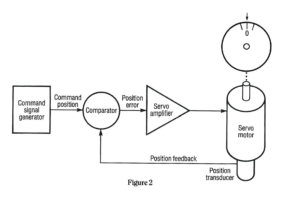
Figure 2 shows a typical closed loop electric servo motor-based motion control system. The system shown is a rotary system. The concepts discussed apply equally to linear systems. The major components are:
- Servo Motor-Converts winding current to mechanical torque, producing the “motion” in the motion control system.
- Position Transducer-Transmits motor shaft position feedback to the comparator.
- Comparator-Receives and compares two signals. The position feedback from the position transducer is compared to the command position signal. The output from the comparator is the difference between the two and is called the position error.
- Servo Amplifier-Converts the comparator output signal (position error) to current which is applied to the servo motor winding. The output of the servo amplifier is connected in such a way as to minimize the position error signal by causing the servo motor to rotate in the direction that yields zero error.
- Command Signal Generator-Provides the desired or command position signal which tells the motion control system how to move.
The major components are connected to provide movement of the motor shaft that is the same as the command position signal. The system components provide the means for a design engineer to turn a motion concept into a working system.
The block diagram shown in Figure 2 is the basis for a broad variety of systems. The basic concept used here is called negative feedback. The output of the system – the actual motor position – is measured and compared to the commanded position. The goal is to make both positions the same-zero error.
Assume that the system has been turned on with the motor shaft at 0 deg and the command generator at 0 deg. The system would be at rest. There would be no motion. The comparator compares the 0 deg command with the 0 deg position feedback. The result of that comparison is called position error. In this case, it is 0, so the amplifier would not produce any impulses to move the motor. The system is at rest.
Now, let’s assume that some outside force or torque moves the motor shaft 1 deg CW (clockwise). The position feedback signal is now 1 deg CW, but the command signal is still 0 deg. The comparator detects this difference and responds by commanding the amplifier to produce CCW (counterclockwise) torque.
The CCW torque turns the motor shaft CCW in response to the outside torque which moved the shaft CW. Since the system activity is continuously monitored, the motion of the shaft in the CCW direction is sensed by the comparator. It responds by decreasing its position error signal to the amplifier. As the motor rotates back to its 0 deg position, the position error decreases until the motor shaft is at 0 deg. The comparator’s output is 0, and the system is at rest.
The same sequence of events occurs in reverse if the motor shaft is displaced in a CCW direction. All closed loop servo systems use components that are bi-directional and provide equal response in both the CW and CCW directions.
Again, assume that the system is at rest. The motor shaft position is 0 deg, and the command position is 0 deg. Now, let’s cause the command generator to produce a command of 1 deg CW.
The comparator responds with a position error that causes the amplifier to produce CW torque and therefore CW shaft motion. As the motor shaft moves toward 1 deg CW the position feedback signal moves towards 1 deg CW and the comparator reduces the position error signal or difference. When the motor shaft reaches 1 deg CW, the position feedback is 1 deg CW. The comparator position error is 0, thereby yielding zero motor torque. The system is again at rest but at a new position. A 1 deg CCW position command signal yields a similar but reversed response from the closed loop servo system and the shaft would be at rest at 1 deg CCW.
The system response to both a shaft disturbance and a command signal change is very similar. The output shaft of the motor moves in such a way as to make the motor shaft position equal to the commanded position. It follows that if the command signal was changed to any degree position, the system would respond by moving the motor shaft to that commanded position.
Real world servo motion control systems have certain limitations that do not yield the ideal performance described above. Some of the most common limitations are:
- The amplifier and motor have limits as to how much power (torque) they can produce. If the motor shaft load is more than can be overcome by the motor and amplifier, the system will stall.
- The comparator and feedback devices are not perfect and cannot detect changes in shaft position that are less than a hundredth of a degree (+/- .01 degrees). This limitation produces motor shaft position errors that are not detected and therefore not responded to.
- All servo system components have limitations on how rapidly they can respond to changes. This limitation can cause the motor shaft to respond imprecisely to rapid command sequences or changes in load. In the extreme case the system can become unstable; system response may be so slow that by the time it responds, the motor shaft may already be moving in a different way. This type of problem is called instability or oscillation and can actually cause the system to never come to rest or remain hunting for the commanded position indefinitely.
To a large extent, all of these system limitations can be compensated for in the design of an actual motion control system. Systems with positional accuracies of a few millionths of an inch are possible within today’s design capabilities.
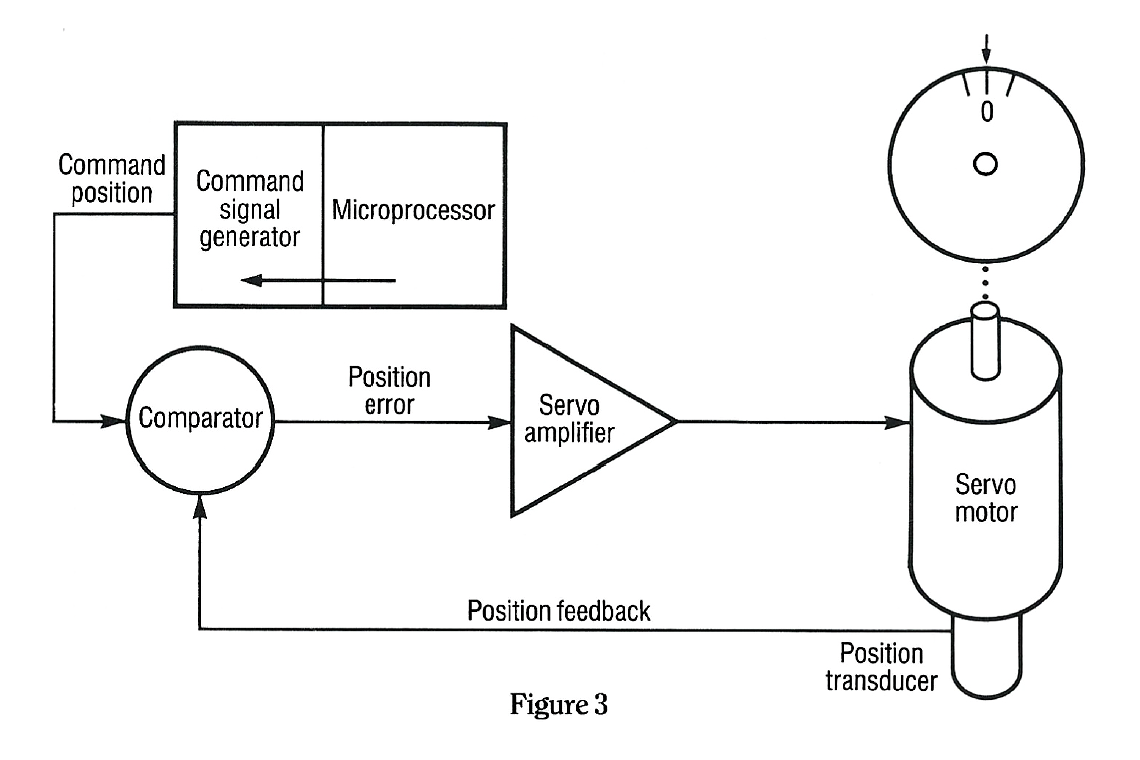
Figure 3 shows an expanded block diagram of a typical motion control system. The key element added is the microprocessor. No single component has enhanced motion control technology like the application of a microprocessor to the command generator section. The microprocessor can provide both simple and complex commands to the comparator section.
These commands, as was shown earlier, provide precise movement of the motor shaft. The microprocessor can store a group of commands in its memory and execute them in a sequence or as individual commands based on logical decisions concerning external events.
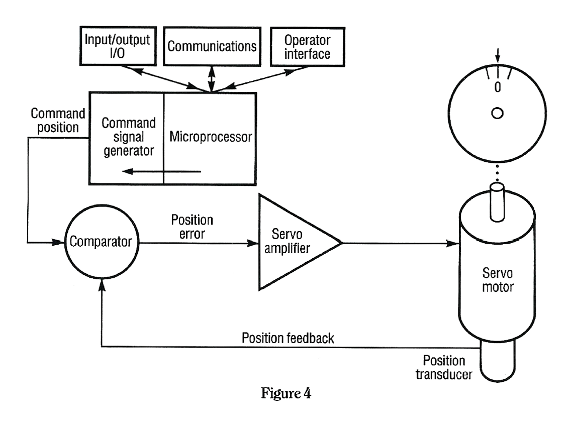
Figure 4 expands further on the motion control system block diagram. The microprocessor’s role has been expanded to control and coordinate the functional relationships between the motion requirements, machine input/output, communications with other devices and the human or operator interface. In many applications this coordination requirement is just as demanding as the motion control.
- The input/output or I/O functions of a motion control system usually involve interfacing with the balance of the machine. Push buttons, limit switches, indicator lamps and solenoids are examples of l/O functions frequently required in industrial applications. Another use for I/O in motion control systems is the interface to other machine control devices such as industrial Programmable Logic Controllers (PLC).
- Modern industrial control systems may have a system or host computer that coordinates the activities of many types of industrial controllers. Motion, temperature, logic and measurement systems may need to be coordinated to produce a particular part. This type of coordination is typically done by linking all these controllers to the host computer via communication ports on the various controllers. Communications between industrial controllers is presently one of the most debated topics in the industry. Hardware configurations and communications protocols are still not fully standardized from vendor to vendor and user to user.
- The human or operator interface allows the motion controller to “talk” to the operator. Typical operator interface devices are:
- Push buttons
- Indicator lamps
- Thumbwheel switches
- Alpha numeric displays
- Keypads
- CRT terminals
These devices are located near the machine operator and are used by the operator to make changes in the motion control process, such as speed or distance. They also allow the operator to monitor the motion controller, by providing diagnostic and data messages.
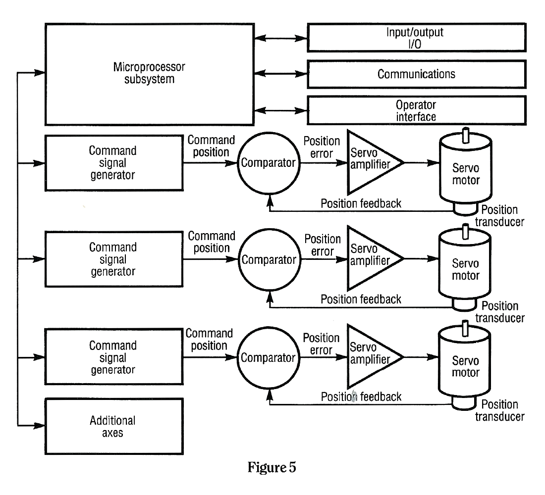
A multi-axis motion control system is shown in Figure 5. In some applications it is necessary to coordinate the motion of two or more axes to create a complex part.
As can be seen in Figure 5, a multiaxis servo controller can be configured around a single microprocessor that generates the motion commands for all the axes as well as tend to the I/O, communications and operator interface. This single microprocessor strategy is somewhat limited when managing high speed applications because the microprocessor has to handle a wide variety of tasks at once.
For example, if two of the motors are moving, the microprocessor is generating two motion commands. While generating these commands, a host computer may send over a request via the communications port and the operator may be requesting a change to start up the third motor. It is easy to see that as the number of requested activities goes up, the microprocessor has less time to spend with each individual task. This type of microprocessor, time management bottleneck is one of the most challenging engineering software problems for the motion control design engineer.

The block diagram in Figure 6 is expanded again to reconfigure the pieces of a modern multi-axis motion controller. Here a master processor has been added and each motion control axis has its own microprocessor for command generation.
This configuration allows higher speed and increasingly complex applications to be handled without running into the time-management bottleneck. The master processor tends to the I/O, communications and operator interface. The difficult task of command generation has been downloaded to the individual axis microprocessors. This configuration can also better handle multiple axes.
The modern motion control system is much more complex than the overview presented here. In reality, the microprocessor is required to do other tasks not covered here, such as:
- Monitor and report on the internal operation of power supplies, memory, high speed logic operations etc.
- Monitor and report motion control errors such as motor or amplifier overloads, hardware failures, disconnected wires or servo runaway.
- Communicate with the outside world of host computers and operator interface devices with a myriad of formats and protocols.
- Monitor and tune the servo response parameters so the motor amplifier is stable and provides smooth operation.
All of these tasks must be done continually to provide a solid motion control system that is reliable and easy to use. The advances in microelectronics and power electronics continue at a rapid pace, forcing manufacturers to produce a new product every two to three years so as not to be left behind in the industry.
 This rapidly changing motion control marketplace provides challenges and opportunities for vendors and users alike. The opportunities lie in applying modern motion control systems to the factory production floor and reaping the benefits of increased productivity and quality. The challenges involve keeping up with a technology that is new to many and rapidly changing. Users must be willing to make an investment in time and energy to keep current with the state of the art.
Industrial Indexing Systems, Inc. has been providing industrial motion control systems for over four decades. We led the industry by shipping the first microprocessor-based motion control system over 45 years ago. IIS continues to lead the industry with a complete line of motion control system products.
The system philosophy at IIS means that all aspects of the motion control requirements are analyzed and specified. The system philosophy means we can supply a completely tested system with motors, controllers, software, documentation and NEMA enclosures. The system philosophy means no unpleasant surprises when you integrate our motion control system into your application.
